


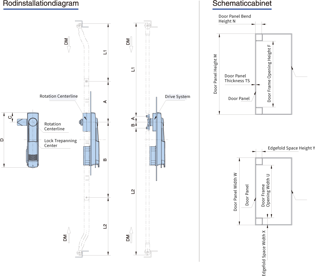
Rod Length calculation method
Central door lock body rotation certer line
coincides with the connecting rod length calculation:
L1=F/2-A+(DM-2)
L2=F/2-B+(DM-2)
Central door lock body rotation certer line
coincides with the connecting rod length calculation:
L1=F/2-A+(DM-2)
L2=F/2-B+(DM-2)
Door center coinciding with the center line
of the lock rod length calculation:
L1=F/2-[A+(D/2-C]+(DM-2)
L2=F/2-[B-(D/2-C]=(DM-2)
Note:If connections (eg LG03 LOG9F),Should lose connections
The effective length, the calculation method is suitable for the installation of rod seal
The length of the calculation; its calculation method for reference only and should be used to consider
The actual installation conditions rod;
DM: Transmission telescopic stroke code
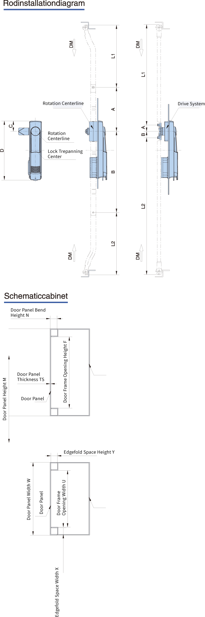
F: door opening height
The effective length, the calculation method is suitable for the installation of rod seal
The length of the calculation; its calculation method for reference only and should be used to consider
The actual installation conditions rod;
DM: Transmission telescopic stroke code
F: door opening height